1.5.7 - Ping Pong Assembly
1.5.7 - Ping Pong Assembly
Section titled “1.5.7 - Ping Pong Assembly”Custom Mechanism: This guide covers the physical assembly of the Ping Pong Launcher add-on for your XRP.
🏗️ 1. Base Mounts We start by attaching the foundational mounts directly to the XRP chassis.
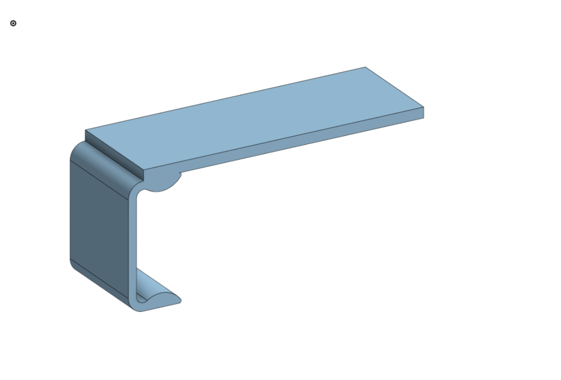
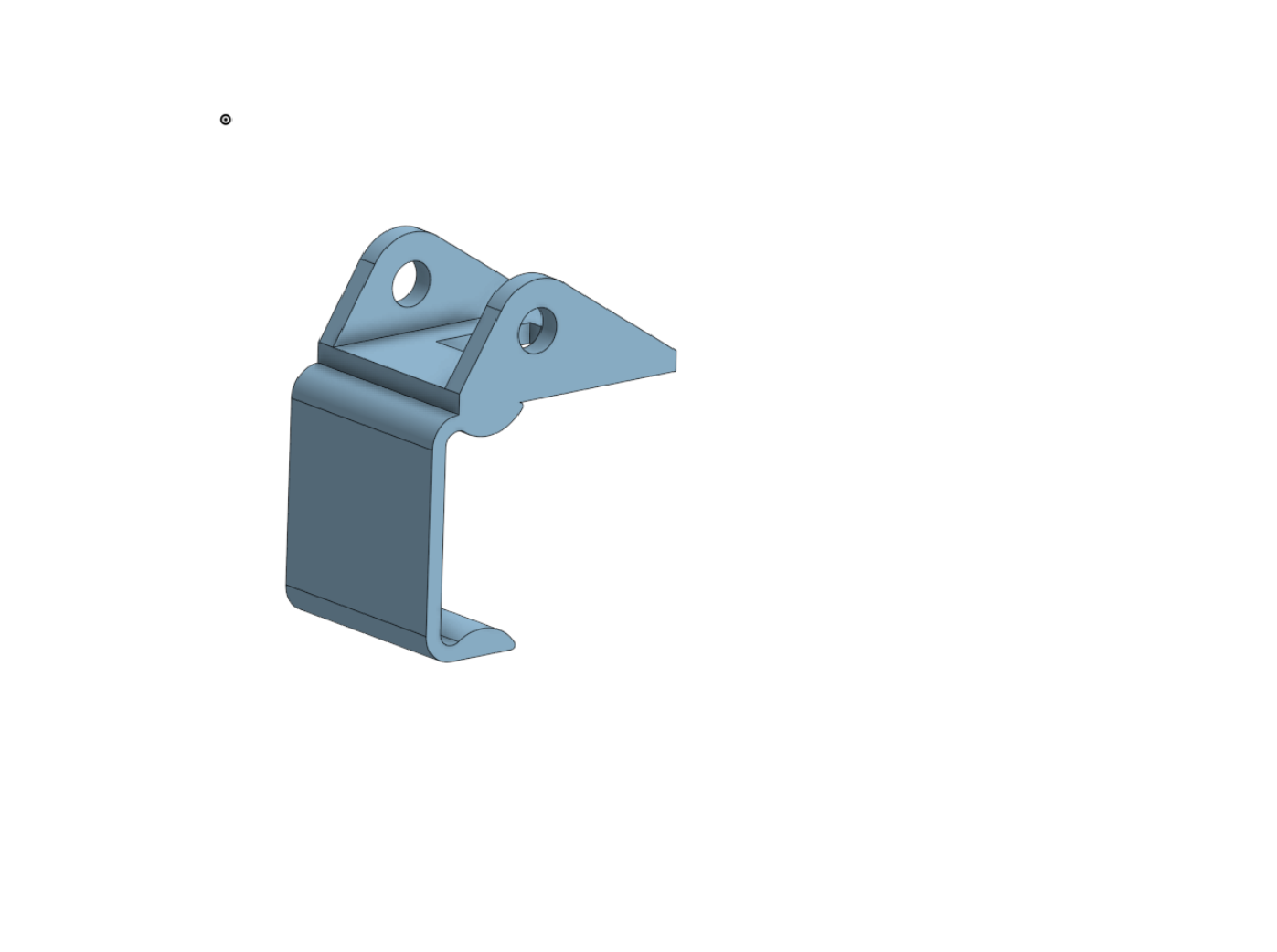
Main Assembly Mount Mounts to the XRP to attach the main structure and pivot. A standard 10-32 bolt is used as the axle.
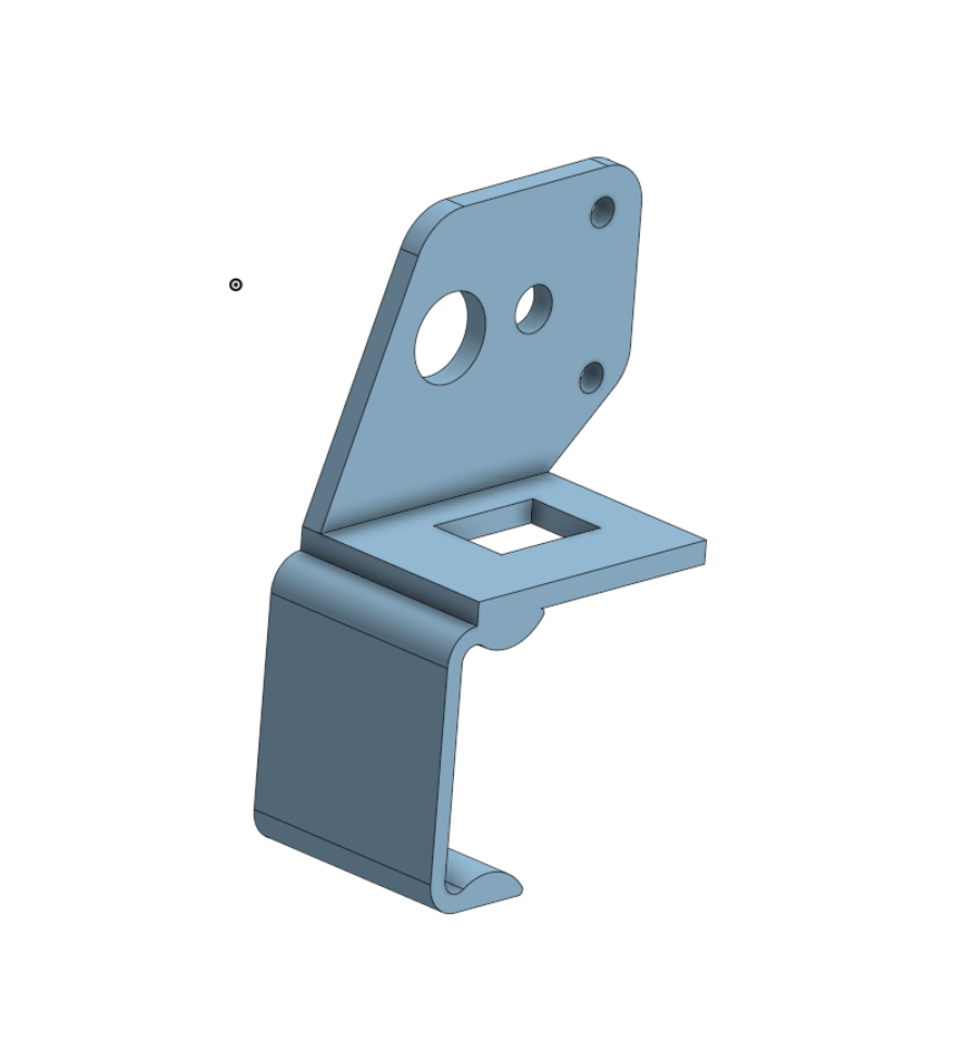
Winch Motor Mount Mounts to the XRP to hold the winch motor. You will use zip-ties to secure the motor to this printed frame.
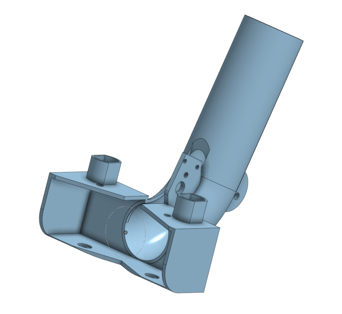
⚙️ 2. The Core Structure Building the main body of the launcher.
Launcher Main Body The core assembly part where the shooter flywheels and motors attach. The 6V motors have a friction fit, and the red motor uses zip-ties to attach to the frame.
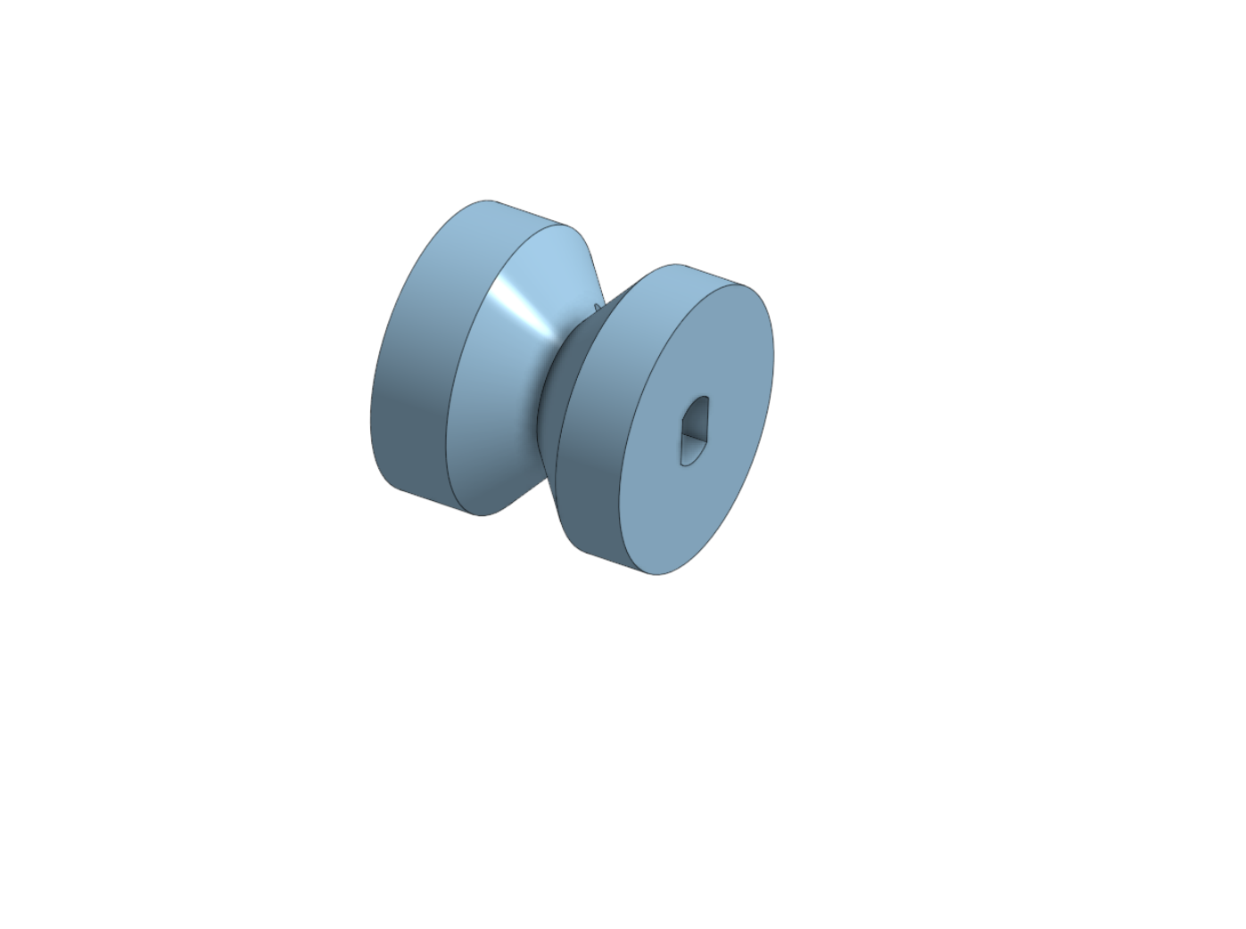
Ball Feeder Feeds the ping pong balls into the intake and rolls them out to be sent through the flywheel at a consistent rate.
🏎️ 3. Motors & Drivetrain Assembling the high-RPM flywheels and angle adjustment mechanisms.
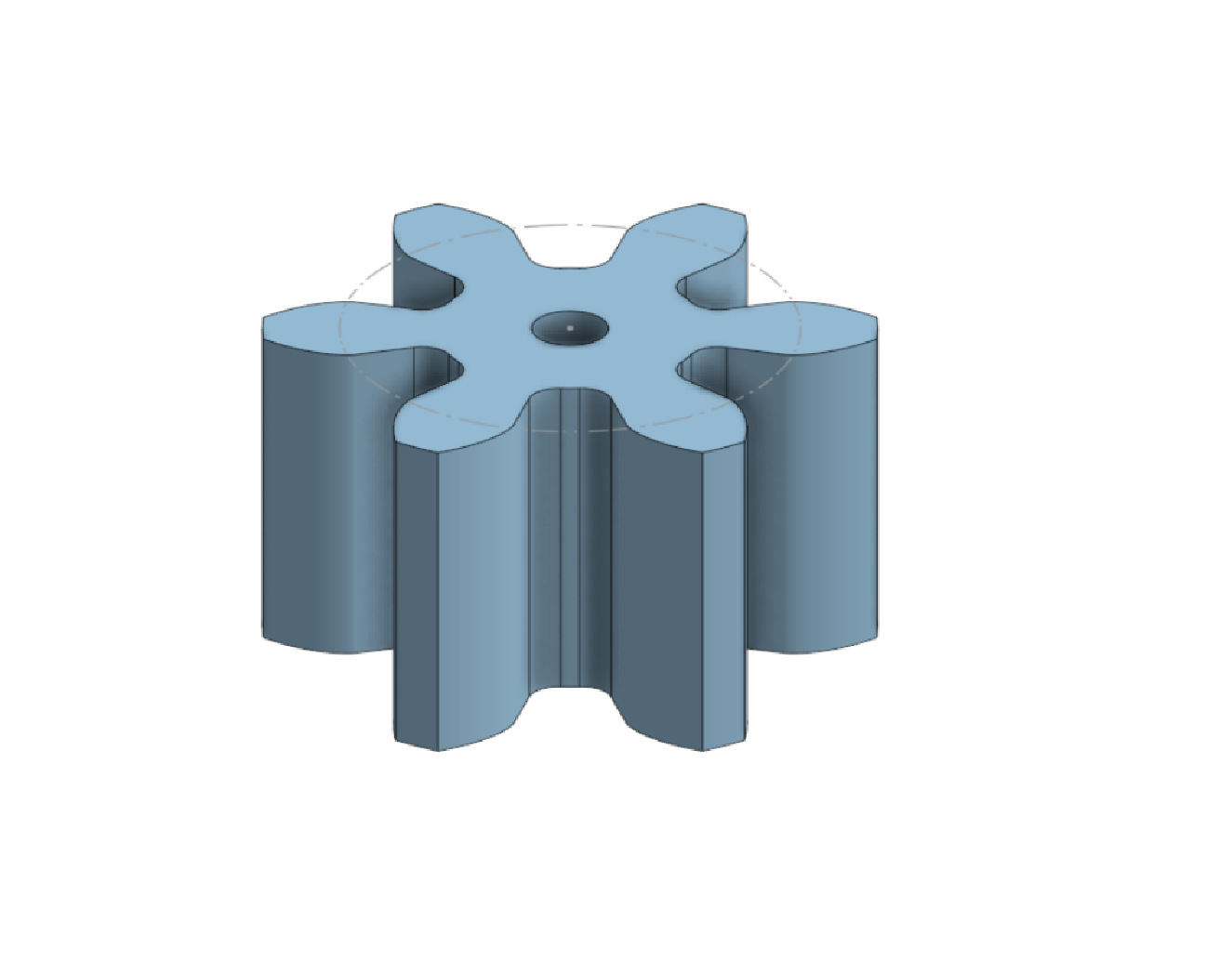
Shooter Flywheel The main shooting wheel. Wrap this in rubber bands to create friction against the ball. It has a gear mesh attached for a 4:1 ratio to shoot the balls at high speeds.
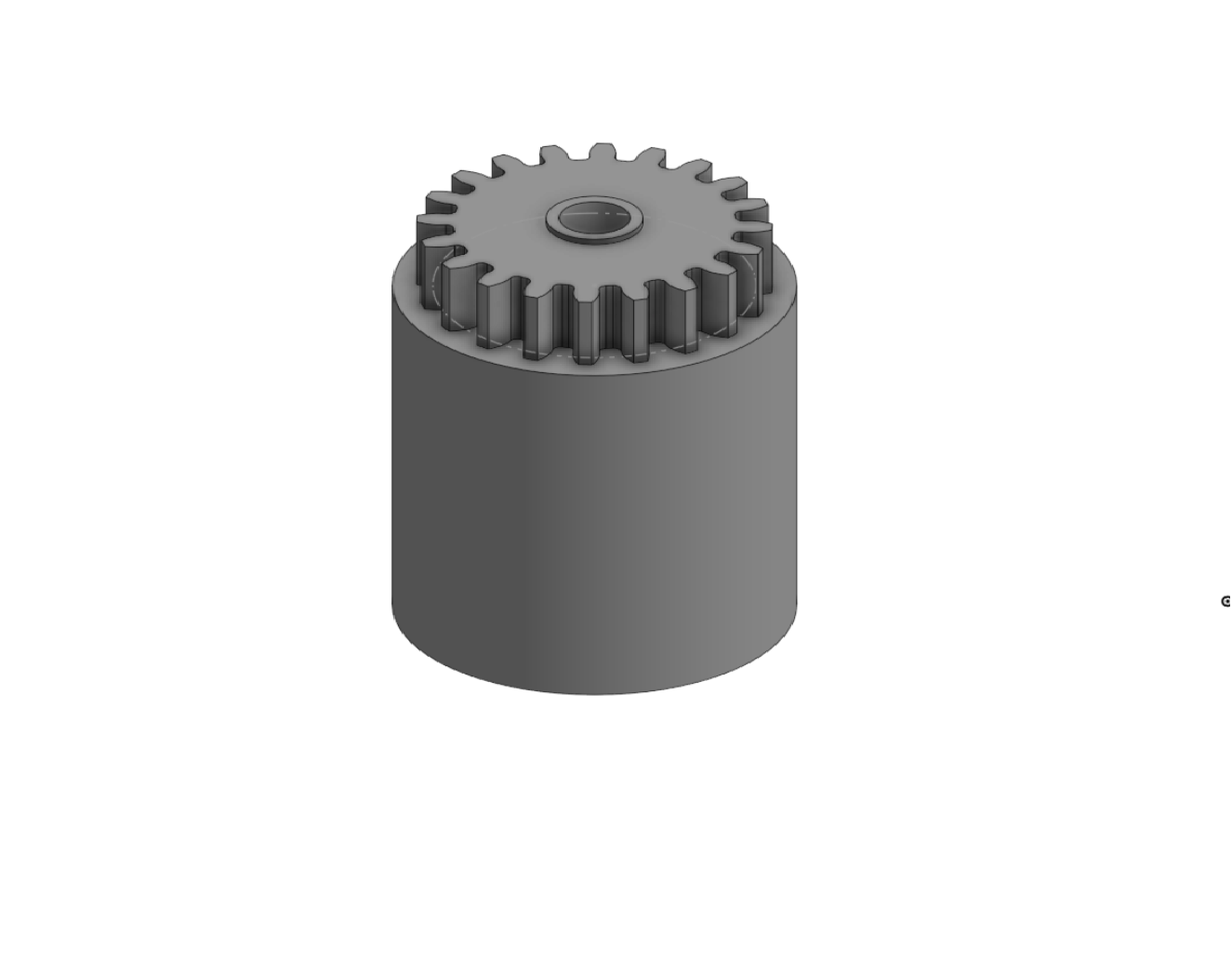
Motor Driving Pinion Attaches directly to the small 6V motor shaft to drive the main flywheel. Requires the Gear Generator FeatureScript in Onshape: Access FeatureScript Here
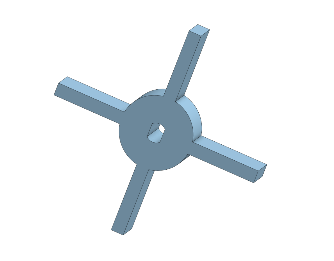
Winch Roller A small roller to pull and release a string, allowing you to control the shooter angle (elevation) via code.
🔌 4. Control Systems Mounting the brains of the operation.
Electronics Board A dedicated mounting board. You will hot-glue your Arduino and L9110S motor driver to this plate to keep your wiring clean and safe.