1.5.8 - Launcher Wiring
1.5.8 - Launcher Wiring
Section titled “1.5.8 - Launcher Wiring”Custom Electronics: This manifest defines the wiring for an Arduino Pro Micro acting as a sub-controller for the XRP.
🧠 Method & Reasoning The standard XRP motors are too slow for shooting a ping pong ball, and the XRP board doesn’t have enough motor ports for our design. We solve this by adding custom electronics:
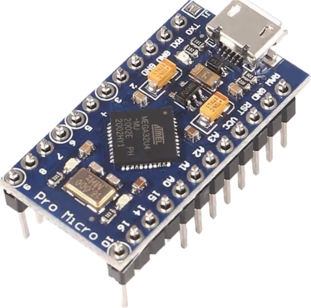
- 1. The “Smart Controller” (Arduino Pro Micro): The Arduino takes the single command from WPILib (e.g., “Shoot at 80% speed”), does the math, and translates it into the specific dual-pin hardware signals needed by the motor driver.
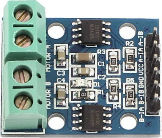
- 2. The “Heavy Valve” (L9110S Motor Driver): This chip acts as a heavy-duty electronic valve. It connects directly to the 6V battery to pull high current, and waits for a tiny, low-current signal from the Arduino to tell it how much power to let through. This keeps dangerous electrical current isolated from your delicate XRP brain.
🔌 Master Wiring Table Follow this table precisely. Ensure your robot is powered OFF and the battery is unplugged before making these connections.
| Connection Group | From (Component : Pin) | To (Component : Pin) | Logic/Voltage | Purpose |
|---|---|---|---|---|
| Control Signal | XRP SERVO2: Signal (IO17) | Pro Micro: Pin 2 | PWM | Signal from WPILib |
| Common Ground | L9110S: Ground (GND) | XRP SERVO2: Ground (GND) | 0V | Completes the circuit |
| Arduino Power | XRP SERVO2: Power (Center/Red) | Pro Micro: RAW | 5V | Powers the Arduino |
| Motor A Drive | Pro Micro: Pin 5 & 6 | L9110S: A-1A & A-1B | 5V Logic | Speed/Direction A |
| Motor B Drive | Pro Micro: Pin 9 & 10 | L9110S: B-1A & B-1B | 5V Logic | Speed/Direction B |
| Motor Power | XRP Battery: Red Wire | L9110S: VCC | 6V Battery | High Current Supply |